Montag, Dezember 10, 2018

SimVimCockpit V0.9.28

In this new version some new functionalities are implemented. I tested two of them and they do work
Find below the description of how to use it:

1. Bus Voltage limits for gauges

The definition of a bus voltage limit let's you specify a limit (e.g. 20V) when a specific system or instrument should stop to work. In my example I want the fuel indicators to switch off when the bus voltage drops below 20V. The option f=x is still needed, especially if you want the instruments to go off when you switch off the battery switch.
Remark: This logic could be improved. Additionally since there is a X-Plane dataref for that voltage limit: sim/aircraft/limits/red_lo_bat_volt=20.

This is the code in data.cfg:
[Bus 1]
P30.0 20
P30.1 20
[Output]
P30.0 Fuel_Level_Tank1  f=x
P30.1 Fuel_Level_Tank2  f=x


2. Gauge calibration

This is a very useful feature. The calibration is done within X-Plane by calling up the plugin function "Gauge calibration" of the SimVimCockpit plugin.
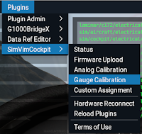


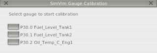
In the first window you select the gauge. In the second window you tune to the "Gauge position" by observing your instrument until it indicates the correct value. Then you set the corresponding "DataRef Value". Hit "Add key point" and continue for other "Gauge positions". The sequence does not matter. Important: add a keypoint for zero too.
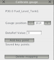


SimVimCockpit is storing these values in a new file "gauges.cfg" in the SimVim folder. Depending on your gauge, you might do a unit conversion. X-Plane uses [kg] and my gauges are in [gal].

Code in gauges.cfg:
P30.0 0,19.7,39.4,59,79.4 0,1680,2430,3150,4095
P30.1 0,19.7,39.4,59,79.4 0,1680,2430,3150,4095


Freitag, November 16, 2018

Condition on parameter - Low bus voltage

I took this feature to the next level.

The previous situation with a link between a switch and an instrument does not reflect the true logic of an small airplane. The new idea is when the bus power drops below a certain value, some instruments go off. The BATTERY SWITCH has no effect. For that you have to use "BUS_1_VOLTS". Imagine your battery in the airplane is dead, you can use the switch, but no reaction on the instruments. Or what if the generator fails during flight and you do not charge the battery. After a while you will get some electrical instruments failure. How exactly the behaviour is, I have to check on a real aircraft.

Remark: in the X-Plane C172, if the voltage drops below 20V most virtual instruments go off, like GPS and fuel indicators. Temperature and pressure indicators don't go off. I tested that. The corresponding dataref for low voltage is sim/aircraft/limits/red_lo_bat_volt. Now if the condition is also set to 20V, also the hardware instruments go off when voltage is below 20V. Which is nice to observe.

The syntax for the condition is:
<pin number> <parameter>
1 Bus_1_Volts

Here the relevant lines of the data.cfg. In yellow the condition and comparison of that condition.

[Conditions]
1 Bus_1_Volts
# -----------------------------
[Input]
S8.0 Beacon_Light
S8.1 Battery1_Switch
S8.2 Avionics_Master_Switch
S8.3 Bus_Cross_Tie
E8.5 Baro_Setting
# -----------------------------
[Output]
P30.0 Fuel_Level_Tank1  r=0,19.7,39.4,59,79.4 m=0,38,56,72,100   c=C1>20   f=x
P30.1 Fuel_Level_Tank2  r=0,19.7,39.4,59,79.4 m=0,38,56,72,100   c=C1>20   f=x
P30.2 Oil_Temp_C_Eng1  r=0,80,160,290         m=0,42,64,100   
P30.3 RPM_Engine1.      r=0,2260               m=0,100

Sonntag, November 11, 2018

Condition on function

Finally, I figured out / understood the syntax of "conditions". The goal was to implement the logic if the BATTERY SWITCH is off, then also all COIL-GAUGES are switched off and indicating no value. In SimVimCockpit 0.9.27a the new flag "x" makes this possible. The description below explains how to use it.

Two steps are needed:

1. add condition to PWM output. In my case the BATTERY SWITCH is connected to multiplexer Pin 8.1. The logic is the following: if the condition is met (SWITCH ON), then the function (GAUGE) is active. If condition is not met (SWITCH OFF), then the function is inactive and values go to zero.
Syntax: c=S<Pin number>
c=S8.1

2. add the flag to set output values to zero if the specified condition is met.
In this case here, if BATTERY SWITCH is ON also the COIL GAUGE will show the values.
The flag works on PWM (coil instruments), Stepper and Servo.
Syntax: f=x
f=x

Option: add the mode when no hardware (switch, button) is assigned to a Arduino pin.
Syntax: S<Pin number> Mode_Switch
S8.1 Mode_Switch

Here is the current version of my "data.cfg". Marked yellow the condition and flag:
*1-1U1
# written by VAKA Nov 2018
# -----------------------------
# RJn = Connector number
# A or B = jumper setting on Breakout Board
# Dn or An = pin numbers on Arduino
# RJ1 Digital In:  A=D8,  B=D9 
# RJ2 Digital In:  A=D10, B=D11
# RJ3 Digital In:  A=D12, B=D13
# RJ4 Analog  In:  A=A0,  B=A1
# RJ5 Analog  Out: A=D30, B=D31
# RJ6 Digital Out: A=D40, B=D41
# -----------------------------
[Input]
S8.0 Beacon_Light
S8.1 Battery1_Switch
S8.2 Avionics_Master_Switch
S8.3 Bus_Cross_Tie
E8.5 Baro_Setting
# -----------------------------
[Output]
P30.0 Fuel_Level_Tank1 r=0,19.7,39.4,59,79.4 m=0,38,56,72,100 c=S8.1  f=x
P30.1 Fuel_Level_Tank2 r=0,19.7,39.4,59,79.4 m=0,38,56,72,100 c=S8.1  f=x
P30.2 Oil_Temp_C_Eng1 r=0,80,160,290 m=0,42,64,100 c=S8.1  f=x
P30.3 RPM_Engine1 r=0,2260 m=0,100
# -----------------------------
[Startup]
XPDR_CODE v=7000
Com1_Active_6 v=119625
Com1_Stby_6 v=134125
Beacon_Audio_Switch v=0


10s Videoclip:


Mittwoch, Oktober 24, 2018

Stabiler Schalter von NKK

Für ein schönes klassisches analog Cockpit habe ich diesen massiv gebauten Schalter von NKK beschafft. Der Typ ist S-1A und schaltet ON/OFF. Als Anschluss habe ich Lötösen gewählt. Kosten: 4 €. Mit Schraubanschluss kostet der Schalter fast das doppelte.

For a nice and classic analog cockpit I have purchased this heavy-duty switch from NKK. The type is S-1A and it switches ON/OFF. I have chosen the solder-lug type. The cost is 4 €. With screw-terminal the price is twice as high.

Sonntag, Oktober 21, 2018

PWM Board am Breakout-Board

Ein weiteres Modul habe ich nun mit dem Breakout-Board verbunden: Das PWM Board mit dem Analog-Spulen-Instrumente angesteuert werden können.

I connected the next module with my breakout-board:
The PWM board which connects analog-coil-instruments.


Diese drei Instrumente laufen nun. Die Skalenabstimmung wird über "data.cfg" gemacht.
Beispiel:
P30.2 Oil_Temp_C_Eng1 r=0,80,160,290 m=0,30,65,100

These three instruments are running. Calibration is easily done within the "data.cfg".
Example:
P30.2 Oil_Temp_C_Eng1 r=0,80,160,290 m=0,30,65,100


Bemerkung: in SimVimCockpit 0.9.27a, datiert 22 Nov., erzeugt das PWM Modul nun den ganzen Bereich von 0 - 5V. Das macht den Umbau und Kalibration von Spulen-Anzeigen einfacher. Vorher war ein kleiner Fehler in der Firmware welcher den Bereich auf 0 - 4.5V eingeschränkt hat, beim Einschalten vom ARDUINO Board das PWM Modul 5V abgegeben hat.

Remark: in SimVimCockpit 0.27a dated Nov. 22, the PWM drives now full range from 0 - 5V (4.9 to be exactly). This make the calibration of coil-instruments easier. Before there was a minor bug limiting the range between 0-4.5V, but when powering up the ARDUINO board PWM sent 5V.

Montag, Oktober 08, 2018

Multiplexer Board mit RJ45

Als nächsten Schritt möchte ich eine auf SimVimCockpit zugeschnittene Multiplexer Leiterplatte (PCB) herzustellen. Diese hat eine fest montierte RJ45 * Buchse und je ein +5V und GND pin **.
* Option 1: IDC Steckerleiste
** Option 2: zusätzlich je ein Pin für L und D Signal

This is an idea of a dedicated Multiplexer PCB for the specific use with SimVimCockpit. It has an RJ45 * socket and one pin each for +5V and GND **
* Option: IDC terminal
** Option 2: additional one pin each for L and D signal

Samstag, Oktober 06, 2018

Setup with Arduino, Breakout Boards and Multiplexers


Aufbau eines Arduino Controllers mit zwei Breakout Printplatten und zwei Multiplexer. Die Verbindung zw. Arduino und Breakout Board geht über ein 25 poligen D-SUB 25 Stecker. Die Breakout Printplatte ist mittels Jumper in "Board A" und "Board B" konfiguriert. Die Verbindung zw. Breakout Board und Multiplexer geht über RJ45 Stecker und ein normales aber kurzes Ethernetkabel. 

Setup of Arduino Controllers with two breakout boards and two multiplexer. The connection between Arduino is done via a 25 pin D-Sub connector. The breakout board is set to "Board A" and "Board B" by jumpers. The connection between the breakout boards and multiplexer is done via RJ45 connectors and a standard but short Ethernet cable.


Das ist die SimVimCockpit Konfigurations-Datei "data.cfg" :
This is the SimVimCockpit configuration file "data.cfg" :

*1-1U1
# written by VAKA Sep 2018
# RJn = Connector number
# A or B = jumper setting on Breakout Board
# Dn or An = pin numbers on Arduino
# ******************************
# RJ1 Digital In: A=D8,  B=D9
# RJ2 Digital In: A=D10, B=D11
# RJ3 Digital In: A=D12, B=D13
# RJ4 Analog In:  A=A0,  B=A1
[Input]
S8.0 Beacon_Light
S8.1 Battery1_Switch
S8.2 Avionics_Master_Switch
S8.3 Bus_Cross_Tie
S8.4 Nav_Lights
# ******************************
# RJ5 Analog Out:  A=D30, B=D31
# RJ6 Digital Out: A=D40, B=D41
[Output]
L13 Pitot_Heat_Off
# ******************************
# Initial values for X-Plane
[Startup]
Fuel_Level_Tank1         v=10
Fuel_Level_Tank2         v=45
XPDR_CODE v=7000
Com1_Active_6 v=119625
Com1_Stby_6               v=134125
Beacon_Audio_Switch v=0


Freitag, September 28, 2018

Breakout Board 2.0 - bestückt / assembled


Breakout Board 2.0
teilweise bestückt / partially assembled


Montag, September 24, 2018

Breakout Board 2.0 - PCB

Zu meiner Überraschung sind die am Mi 19.9. bestellten Printplatten schon heute am Mo 24.9. angekommen. 😁 Das ist ziemlich wahnsinnig was heutzutage möglich ist.

To my surprise the PCB ordered Wed Sept. 19 have already arrived today Mon Sept 24. That's crazy what possible nowadays.


Dienstag, September 18, 2018

Breakout Board 2.0

Das ist eine mögliche Lösung für ein Breakout Board. Habe 5 Stk. bei JLCPCB bestellt.

Funktionen:
- Bus mit 25 Pin D-Sub Stecker
- Anschlüsse für MUX mit RJ45 Stecker
- 3x Digital Eingänge
- 1x Analog Eingang
- 1x Analog Ausgang (PWM)
- 1x Digital Ausgang (Stepper, LED)
- Schutzwiderstände auf dem Signalbus
- Das Board kann mittels Jumper in eine Variante A oder B geschaltet werden. Damit kann man Board A + B in Serie schalten (Daisychain).


Das ergibt dann total 96 digitale Eingänge (Schalter), 32 analoge Eingänge (Potentiometer), 32 analoge Ausgänge (Spulen-Zeigerinstrumente) und 32 digitale Ausgänge (Zeigerinstrumente mit Schrittmotor oder LED).


This is one possible solution for a breakout board PCB. Ordered 5 pcs. at JLCPCB.

Features:
- Bus with 25 pin D-Sub connector
- connection for MUX with RJ45 connectors
- 3x digital inputs
- 1x analog input
- 1x analog output (PWM)
- 1x digital output (Stepper, LED)
- Safety-resistors on the signalbus
- With jumpers the board can be configured in an A or B version to connect them in series.


This totals to 96 digital inputs (switches), 32 analog inputs (potentiometer), 32 analog outputs (coil gauges) and 32 digital outpus (steppermotor gauges or LED).


Schema / Scheme

Sonntag, September 16, 2018

SimVimCockpit V0.9.22

Gute Nachrichten. Die Beta Version V0.9.22 von SimVimCockpit funktioniert nun auf meinem iMac mit USB Anschluss wieder reibungslos. Die Verbindung zw. X-Plane, dem Plugin und Arduino klappt nun. Auch mehrfaches Wiederverbinden (Reload configuration) funktioniert.

Good news. Beta version V0.9.22. of SimVimCockpit works again with my iMac and USB. The connections between X-Plane, the plugin and Arduino are stable, even after multiple "reload configuration".


Das ist der aktuelle Bauzustand meines Test-Setups.

Samstag, August 18, 2018

Gehäuse für ARDUINO

Gehäuse für ARDUINO
D-Sub 25f mit Signal-Leitungen für RJ-45 Breakout-Board
Housing for ARDUINO
D-Sub 25f with signal-lines for RJ-45 breakout-board.

Mittwoch, August 15, 2018

Gehäuse für MUX

Ein kleines 3d-Druck Gehäuse für den Multiplexer mit Schraub-Terminal von PHOENIX Contact und RJ45 Buchse.


Small 3d-print housing for Multiplexer-Board with Screw-In terminal and RJ45 socket.

Montag, Juli 16, 2018

Making your own PCB


Anstatt die Bastel-Lösung mit einem Prototyp-Board und viel Lötarbeit würde mir ein eigener PCB (Printed Circuit Board) viel besser gefallen.
Mit dem Online-Tool "easyEDA" kann man sich Schemas und danach den PCB Layout erstellen.
Kosten: ca. 15$ pro PCB bei einer Kleinserie von 5 Stk. (made in China)


Instead of a cumbersome prototype-board with a lot of soldering work I would like to have a dedicated PCB.
With the online tool "easyEDA" you can create schemes and PCB layout.
Cost: about 15$ per PCB (made in China)


Samstag, Juli 14, 2018

5V LED

Bei Distrelec (www.distrelec.ch) habe ich mir 5V LED mit integriertem Vorwiderstand besorgt.
Vorteil: diese LED kann man direkt an ARDUINO anschliessen ohne einen extra Vorwiderstand einzubauen.
Nachteil: Lichtstärke ist bei diesem Typ etwas schwach.

I bought 5V LED with integrated resistor at Distrelec (www.distrelec.ch) which can be connected directly to ARDUINO.
Advantage: No need to use an extra resistor.
Disadvantage: Light-intensity is rather low on this type.

Dienstag, Juli 10, 2018

Breakout-Board

Das ist eine Lösung von vielen für ein Breakout-Board welches mit ARDUINO verbunden ist. Ich habe mich für RJ45 entschieden, weil ich Kabel nicht selber bauen möchte. Mit Flachband-Kabel und IDC-Stecker ginge es auch. Der Vorteil von RJ45 Kabel ist, dass sie zusätzlich geschirmt sind. Das ist vermutlich technisch nicht zwingend notwendig, aber es verhindert ungewollte Störsignale.
Mit zwei Breakout-Boards kann man mind. 64 Schalter, 32 Encoder, 32 Potentiometer, 48 Drehspulen Inst. und 16 LED verbinden. Für ein komplexes Cockpit mehr als genug.

This is one solution of many for a breakout-board to be connected to ARDUINO. I decided to use RJ45 because I don't want to build cables myself. It would work of course also with flat-ribbon cable and IDC connectors. The advantage of RJ45 cables is that they are shielded. This is probably not really required, but it prevents unwanted signal-pickup from other sources.
With two Breakout-Boards you can connect at least 64 switches, 32 encoders, 32 potentiometers, 48
Moving-Coil Instr. and 16 LED. Enough for a complex cockpit.


Schema
Breakout Board A

Mögliche Anschlüsse:
32x Schalter
16x Encoder
16x Potentiometer
24x Drehspulen Instr.
16x LED oder Schrittmotoren

Schema
Breakout Board B

Mögliche Anschlüsse:
32x Schalter
16x Encoder
16x Potentiometer
24x Drehspulen Inst.
Hardware

Montag, Juli 09, 2018

X-Plane Dataref-Editor

To check values of specific datarefs you can download and use the "Dataref editor" from X-Plane.
Source: http://www.xsquawkbox.net/xpsdk/mediawiki/DataRefEditor

This plugin will display all datarefs for the airplane you are using. In my case I wanted to check the values for the Fuel-Flow. The output is that it varies between 0.003 and 0.009 kg/sec.

Screenshot of Fuel-flow in the C172:
 idle
full throttle

Sonntag, Juli 08, 2018

FSWeekend in Lelystad / NL : 3. - 4. Nov. 2018

Empfehlung : FS-Weekend in Lelystad / NL : 3. - 4. Nov. 2018

Das ist wohl die grösste Veranstaltung in Europa welche sich mit Flugsimulation und vorallem Homecockpit-Bau befasst. Ich war vor vielen Jahren dort und war sehr beeindruckt.

Intro-Video


Display / Encoder module for Bendix-King Instrumentes

Found this on www.propwashsim.com

It is a nice display/encoder module to build a replica of Bendix-King instruments like a KX155 or similar.

According to www.propwashsim.com it should work together with SimVim.

Design drawback: the position of the controller chip is not ideal, because the display of the orginal Bendix-King is on the very top-edge.
So the replica can not be stacked in a usual way.
For some flightsim-cockpits it may work.

Samstag, Juli 07, 2018

SimVim Wiring Concept


Das ist ein mögliches Konzept um die versch. Module mit dem ARDUINO zu verbinden und dann mit SimVim + XPlane laufen zu lassen. Die Verdrahtungs-Logik wird in den Breakout-Boards gemacht.
Vorteil: Verwendung von fertigen Kabeln (D-Sub DB25 und RJ45)

This is a possible concept to wire/connect the various modules with ARDUINO and run it with SimVim + XPlane. The wiring-logic is done on the breakout board.
Advantage: use of off-the-shelf cables (D-Sub DB45 and RJ45)


Montag, Juni 18, 2018

Multiplexer board and analog input (Potentiometer)


Das ist mein "Standard-MUX-Board". Am Schraub-Terminal werden die Signale 1-16, GND und +5V angeschlossen. GND und +5V sind an den entsprechenden Output-Pin verdrahtet, resp. mit der RJ45 Buchse verbunden. Die 8 Ausgangs-Signale sind SIG, S0, S1, S2, S3, EN, +5V und GND. Ein Standard RJ45 Kabel stellt via einem speziellen Breakout-Board die Verbindung zum ARDUINO Board her. Die Idee dabei ist, die Lötarbeiten und Kabel-Konfigurationen auf ein Minimum zu reduzieren.
This is my "Standard-MUX-Board". A screw-in-terminal allows to connect the input signals 1-16, GND and +5V. GND and +5V are wired to the corresponding pin of the MUX output. The 8 output signals are SIG, S0, S1, S2, S3, EN, +5V and GND are connected to an RJ45 socket. A standard RJ45 cable is then connected to a dedicated breakout-board near the ARDUINO board. The idea is to minimize soldering work and to avoid special cables.

alte ELITE Konsole

Und diese alte ELITE / Precision Flight Console möchte ich mit SimVimCockpit wieder zum Leben erwecken.
Bisherige Lösungen scheiterten nur schon an den maximal 13 analog Achsen (Throttle quadrant, trim wheel, rudder trimm, roll, pitch und evt. verbunden mit Pedalen / Bremse). Die Kippschalter sind die einfache Sache.


Analog Anzeigen / Coil Gauges


Diese alten analog Zeiger-Instrumente (coil gauges) möchte ich mit der PWM Karte betreiben. Natürlich nicht direkt, einige Modifikationen und Einbau von Widerständen ist nötig.
Erfolgreicher Test mit
SimVimCockpit beta 0.9.16.


Quelle: ebay.deebay.comricardo.chdistrelec.chmouser.comdigikey.comconrad.chconrad.de
Suchbegriffe: Voltmeter, Analgoanzeige, coil gauge, coil instrument

Sonntag, Juni 17, 2018

Interface für Cockpit-Module

Dies ist die momentane Lösung für die div. Cockpit-Module.
- Multiplexer-Board (hobby-elektronic.ch, ricardo.ch)
- Screw-In Terminal 8 Pin von PHOENIX contact (DigiKey.ch, Conrad.ch, Aliexpress.com)
- Pfosten-Steckerleiste und Buchse (play-zone.ch, Digikey.ch)
- RJ45 Breakout Board. (Sparkfun, Digikey.ch, shop.boxtec.ch)
- RJ45 Stecker (DigiKey.ch)

Vorteil: ein Einheits-Element für jedes Cockpit-Modul.

Offene Probleme:
- sauberer Anschluss des GND. Mögliche Lösung: 10-fach Terminal
- mechanische Stabilität. Lösung: RJ45 Breakout Board mit Schraub-Befestigung.

Es entstanden zwei Varianten : A) 90° und B) gerade


Verdrahtungs-Konzept mit Flachband-Kabel


Das war die erste Idee ARDUINO mit den div. Modulen zu verbinden.
Ein Flachbandkabel mit IDC Stecker. Aber aufgrund der vielen Signale und eingeschränkten Möglichkeiten mit IDC Stecker habe ich mich dagegen entschieden.

Donnerstag, Juni 07, 2018

Verdrahtungs Konzept


Mit RJ45 Buchsen können die Multiplexer-Board mit dem ARDUINO sicher und preiswert verbunden werden.
Auf dem MUX-Board wird eine Schraub-Klemme die Verbindung zu den Komponenten wie Schalter, Encoder, etc. herstellen. Somit ist alles modular aufgebaut und der Kabel-Wirr-Warr hält sich in Grenzen.

Das schöne an SimVimCockpit mit ARDUINO ist dass die Module "hot plugging" fähig sind. Man kann also im laufenden Betrieb die Stecker trennen und wieder verbinden ohne das der Signal-Fluss verloren geht. Andere Lösungen können das nicht.

Beschaffungs-Quellen:
www.digikey.ch  www.digitec.ch  www.hobby-elektronik.ch  www.conrad.ch  www.distrelec.ch www.play-zone.ch


Dienstag, Juni 05, 2018

X-Plane + SimVimCockpit + ARDUINO: Proof of concept

Um das Konzept zu bestätigen habe ich folgendes vorbereitet:
- X-Plane 11 gestartet
- SimVimCockpit Plugin "beta 0.9.12" installiert
- ARDUINO Mega 2560 über USB angeschlossen (Ethernet kommt später)
- SimVimCockpit Firmware auf ARDUINO übertragen
- Konfigurations-Datei erstellt und abgespeichert
- 3 Kippschalter an GND und Pin #5-7 angeschlossen

Resultat: Kippschalter-Signale werden an X-Plane übertragen. Somit erste Stufe bestanden.
Urteil: Installation war EXTREM einfach. Nach 10 Min. lief alles.


Montag, Juni 04, 2018

X-Plane 11 + Arduino + SimVimCockpit

Nach vielen Jahren der Abstinenz....

Vor einigen Tagen bin ich auf ein interessantes und vielversprechendes Projekt gestossen:
SimVimCockpit von www.simvim.com

Es geht hierbei um einen neuen Ansatz für den Homecockpit-Bau. Als neutrale Logik-Hardware-Platform wurde ARDUINO gewählt. Dazu kommt ein Plugin von SIMVIM welches die ARDUINO Firmware hochlädt und die Verbindung zw. X-Plane und der ARDUIONO Hardware herstellt. In einem Konfigurator wird dann die eine Konfigurations-Datei erstellt, welche in ein X-PLANE Verzeichnis kopiert wird.

Dies Grafik illustriert das Konzept
Quelle: www.simvim.com


Dieser Ansatz gefällt mir wesentlich besser als die inzwischen doch recht veraltete Lösung von OPENCOCKPITS. Warum?

Weil:
- nur ein Hauptmodul (ARDUINO)
- Ein Hauptmodul kann sehr viele Ein- und Ausgänge steuern (ca. 30 digital und 16 analog)
- in kleinerer Anzahl können Schalter, Encoder und LED direkt angeschlossen werden.
- der ARDUNIO Controller kann auch über Ethernet laufen anstatt USB.
- für Schalter und Encoder gibt es einfache Breakout-Panels die über einen Bus verbunden werden.
  somit kann die Anzahl an digitalen und analogen Ein-/Ausgängen auf bis zu 500 erhöht werden.
- Breakout Panel für den Anschluss Spuleninstrumente sind erhältlich
- Konfigurator ist einfach zu verstehen und zu bedienen.
- Verwendung einfacher Automotive-Schrittmotoren (Zeigerinstrumente) ist möglich
- moderate Preise der Hardware-Komponenten

Nachteil:
- die Datarefs von X-Plane sind im Konfigurator vordefiniert. Mit der nächsten Version von SimVimCockpit sollen "Custom Datarefs" möglich sein.
- nur 1 ARDUINO Controller kann mit SimVimCockpit laufen.
- Schaltungen für 7-Segement Anzeigen und Schrittmotoren sind im Aufbau komplex. Aber da der Trend zu Glascockpit geht, sind Instrumente wie King-Bendix eher am aussterben.


Habe mir nun jedenfalls einen ARDUINO MEGA bestellt. In ein paar Tagen kann ich hoffentlich schon etwas zeigen. Das Ziel ist es eine ausgeschlachtete ELITE Yoke-Control-Unit zusammen mit X-Plane 11 wieder zum Funktionieren zu bringen.